What is Stepper Motor and How it Works?
What is Stepper Motor?
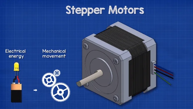
A stepper motor is a device which converts electrical energy into mechanical movement. It supplied dc electricity in a certain controlled sequence which causes rotation. The rotation can be continuous in either the forwards or reverse direction or we can control the rotation in small steps for higher precision control. The motor can even stop at a desired point and hold this position. This is more advanced than a standard dc motor which can only rotate continuously in either the forwards or reverse direction. Therefore stepper motors are far more useful in automation and manufacturing because they offer precision control. That is why we find stepper motors used everywhere from 3d printers, cnc machines, printer scanners and even electronic expansion valves in precision refrigeration systems.
The motor is attached to a motor driver, which basically contains some electronic switches that are capable of turning on and off at high speed. A controller determines when to turn these switches on and off. It usually follows some code to achieve this. The driver is typically a dedicated circuit board specifically designed for that application and the controller can be. For example a plc unit or even a simple cheap little Arduino. The switches will allow electricity to flow impulses through the motor's coils. Every pulse received causes the motor to rotate one step. A typical stepper motor is designed to have 200 steps, this means it would take 200 pulses to complete a full rotation of the shaft. A full rotation would be 360 degrees. So if it takes 200 steps to achieve this, then 360 degrees divided by 200 steps means each step causes the shaft to rotate 1.8 degrees. The speed of switching and the order the switches are controlled in will determine the rotational speed and also the direction of rotation.
There are various types of stepper motor. This type is a hybrid motor which is the most commonly used. We see the motor consists of two end caps and the main body. The shaft sticks out from one end and the electrical connections are usually found at the opposite end. Inside the motor we see there are two bearings attached at either end of the shaft. These hold the shaft in place and ensure a smooth rotation attached to the shaft we find the rotor the rotor and shaft rotate together. The rotor is a permanent magnet which has two halves known as cups. One cup is the North Pole and the other is the South Pole. There are a number of teeth carved into the outer surface of each cup. The teeth of the two cups do not align. They are offset from each other so that the teeth of one cup aligns with the gaps of the other cup. Surrounding the rotor is the stator. The stator remains stationary and does not rotate. This consists of a number of coils of wire which surround the rotor. The coils are not all connected together.
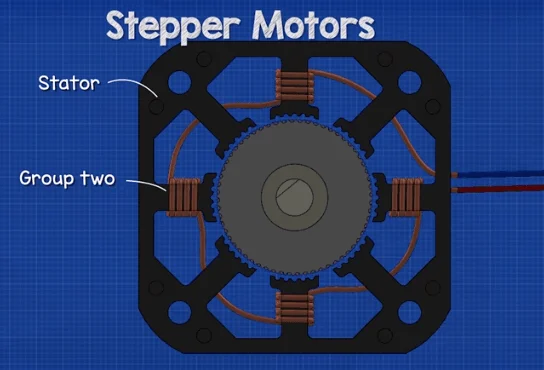
In this example there are eight coils which are connected in two groups of four. The driver will control when electrical current can flow through these coils, this creates an electromagnetic field which causes the rotation. There are teeth surrounding the inner perimeter of the stator also. These are used to enhance the precision of the motor and create magnetic alignment. The rotor has more teeth than the stator.
For example the stator might have 48 teeth while the rotor has 50 teeth. This difference means not all the teeth will be able to align at the same time. When one set of coils is energized the coils will form electromagnetic fields with north and south polarities. The rotor is a permanent magnet and this will interact with the stator's electromagnetic field causing the rotor to turn. The coils will turn on and off and the polarity of a coil's electromagnetic field will reverse each time it turns on, this causes the rotor to rotate because the stator coils will attract and repel the rotor cup's magnetic field.
How does a stepper motor work?
We know that magnets will interact the opposite ends will attract while their like ends repel. When current flows through a wire it creates an electromagnetic field. If we wrap the wire into a coil it creates a larger stronger electromagnetic field with a north and South Pole. We reverse the polarity by changing the direction of current. We can turn the magnetic field of the coil on and off by simply allowing or stopping the flow of current but the magnetic field of a permanent magnet is always on. If we place a magnet centrally and allow it to rotate freely we can use other magnets to rotate this. We can also place electromagnets around this and control the rotation by controlling the current flowing through each coil. The more coils we use the more precise the rotation. A simple way to control the coils is with an h bridge, if we imagine the motor has two coils and each coil is connected to four switches, if we close which is 1 and 4 coil 1 polarizes attracting the rotor. Then we close switches 5 and 8 causing the rotor to turn because of the attraction and repulsion of the magnetic fields, then we close which is 2 and 3. The polarity has now reversed and the rotor turns then we close which is 6 and 7 to rotate the rotor again, then we close switches 1 and 4 to complete the rotation. The switch sequence continues causing the rotor to turn reversing the sequence reverses the direction of rotation changing the frequency of switching controls the speed. The switches are electronic instead of manual allowing us to program them to turn on and off with precise timing.
Permanent Magnet Stepper Motor
The Permanent Magnet Stepper Motor is consists of a permanent magnet rotor which is diametrically magnetized. In this simplified version we have four coils connected as two separate pairs. Each pair is connected to a different phase, when pair one energizes the magnet rotates to align with this, the next pair is energized and this causes the rotor to again turn and align the coils keep turning on and off and the current flows in different directions to create the rotation. In this design the motor turns 90 degrees on each step, we could improve this with more coils or more magnetic poles on the rotor.
Variable-Reluctance Stepper Motor
The variable reluctant stepper motor is a little different, this type uses a soft iron ferromagnetic rotor which means this material is attracted to a magnetic field but it is not a permanent magnet. In this design we have four teeth on the rotor. There are three sets of coils each set connected to a different phase. There are different number of coils and rotor teeth this prevents the rotate from all the lining at the same time.
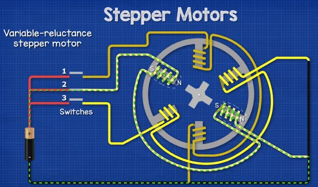
In this case we're going to use three switches to control the motor. When switch 2 closes the coils magnetize and attract the rotor teeth causing it to turn, then switch 3 closes and the rotor turns again to align with the magnetic field, then switch one closes and the rotor turns this sequence then repeats. In this design the rotor turns 30 degrees with each step. There are multiple ways to reduce the step angle for example adding a four phase and more teeth to the rotor.
Hybrid Stepper Motor
The hybrid stepper motor is the most common version used. It is a hybrid because it is a combination of the variable reluctance and the permanent magnet stepper motor. If we look at this simplified version with four coils connected in two pairs we have the actually magnetized rotor meaning the poles are at opposite ends. The rotor has three teeth on each magnetic pole. There are a different number of teeth and coils to prevent them from all aligning at the same time. When we energize the coils they form north and south poles, these interact with the rotors permanent magnetic field. The rotor's South Pole tooth is repelled by the stator's South Pole and is also attracted to the stator's North Pole. Meanwhile the rotor's North Pole tooth is repelled by the stator's North Pole and is attracted to the stator's South Pole, this causes rotation. Then the next set of coils are energized the rotors magnetic field are again attracted and repelled by the status coils causing rotation. This continues with the different sets of coils being energized and the current reversing to change polarity of the coil.
Stepper Motor Controls
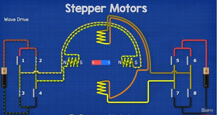
Stepper motor control - There are multiple ways to control the rotation of the rotor. We’ll see some simplified versions of how these work using a permanent magnet rotor. The first method is the wave drive which is the simplest, this is where only one phase is activated at a time to create rotation. The step angle is large and as a result the rotation is not very smooth. The torque of the motor is also low when using this method so it is rarely used then we have full step which is similar except two phases are activated at the same time. The rotor is attracted to both coils so it will instead take the average of the coils and align between them. The torque is much higher using this method then we have half step this energizes a single phase and then two phases and then a single phase and then two phases which provides a much smoother rotation and smaller step angle. The rotor aligns with a coil then the average of two coils then a single coil and then the average because at certain times only one coil is activated, the torque is therefore reduced.


![What Is A Backslash [\]?](https://www.whizzlearning.com/DataImages/Blogs/638054178435160564/backslash-sidebar.webp)


